Scott Townley
Gilbert, AZ
The mobile installation includes a Ten-Tec Hercules II solid-state amplifier with 500 watts output. Going from 100 W to 500 W is 7 dB, or more than a standard S-unit. The Hercules has an available remote control unit, which is really nice to have in a mobile station. The remote displays the selected band and the power output, as well as providing an ON-OFF switch.
This Hercules has some modifications to the DC distribution. See the Hercules page for details.
Amplifier Mounting
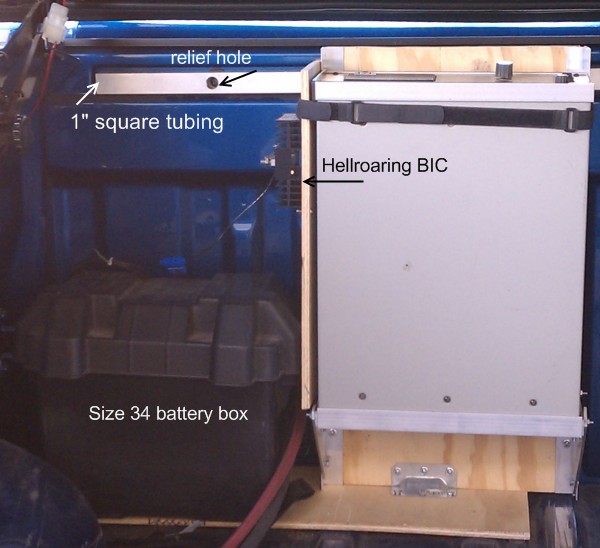
The amplifier is mounted vertically, on the front wall of the bed of a 2008 Toyota Tundra CrewMax. The top rail of the front bed wall has some factory 7mm threaded inserts. The idea was to hang a plywood "floor" for the amplifier from those inserts. A 1" square aluminum tube about 2-1/2' long was fastened via those threaded inserts first (I drilled relief holes on the opposite side of the tube for access to the inserts through the square tube). Then a second set of 1/4" Threadserts (do-it-yourself threaded inserts, similar to rivets) was placed in the square tube, and the plywood hung from the Threadserts.
Angle aluminum was used to build a frame to hold the amplifier to the plywood "floor". The amplifier is mounted face-up, so that I can see the front panel meter and indicator lights during testing and troubleshooting. (Thermally it would probably be better to mount it face-down, so that convection aids the Hercules fan...but practically I knew I'd want to see the front panel). The frame was positioned so that there was as much room as possible underneath the amplifier to accommodate the length of the SB-150 power connector.
IMPORTANT! I have a lid on my pickup truck bed. The amplifier is not exposed to the elements!
Remote Control and Band Switching
The Yaesu FT-100 has a BAND DATA output that provides a BCD-coded digital output corresponding to the selected band, and provides a PTT output to key an amplifier.
The Hercules II has a REMOTE input that allows the band to be selected by applying +12VDC to various lines, as well as a PTT input. For that matter, the Hercules II has a remote control box (model 9423) that allows for power on and manual band selection. The 9423 also displays the selected band, forward power, and fault conditions via LEDs.
Can they play together? Yes they can!
Since the FT-100 has the automatic band switching outputs, I wanted to use those and have the 9423 function simply as a remote power-on with all the display elements. Here's a diagram of what I envisioned:
Making It All WorkOr, Ferrite Is Your Friend
Power, using an auxiliary battery and a battery isolator
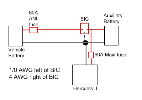
The battery box holds an Optima Red Top (Size 34). Alan (K0BG) recommends a starting battery over a deep-cycle for this application, and his reasoning makes perfect sense to me. The power runs from the battery to the amplifier through one side of a Hellroaring BIC-95150B battery isolator. Alan recommended this particular company as well, and again I agree: they make an excellent unit. The other side of the BIC runs to the engine compartment and the vehicle battery and alternator. You can see the cables for the ignition battery run in the picture, they are 1/0 size welding cables.
The 9-series BIC is actually rated to carry current in excess of the amplifier draw, so in principle I could remove the battery entirely and still operate ("extended battery maintenance period"). But this auxiliary battery setup removes the strain from the vehicle electrical system and keeps the headlights from sending MCW while I'm transmitting. The amplifier actually operates from the auxiliary battery, and the vehicle battery keeps the auxiliary at full charge through the BIC.
Line Diagram of Power Distribution System
| • |
FT-100 BAND DATA drives a Top-Ten devices band decoder. The band decoder translates the BCD "word" to any combination of open-collector outputs to drive relays. |
| • |
PTT output is available, again open-collector. The transistor specs on the BAND DATA PTT are 50 V and 200 mA. |
FT-100
Hercules II
| • |
REMOTE connector band selection is made by asserting +12VDC on a particular pin |
| • |
The FAULT indicator is inverted logic; it's actually "not FAULT". So +12VDC normally, and driven to ground on a fault. |
| • |
PTT input goes to the KEY IN pin, drive to ground. Sinks +12VDC at about 5 mA. |
9423 Remote Control
| • |
The Band Select switch routes +12VDC to either (1) a NC relay, in the Power Off position, or (2) individual pins of the REMOTE connector. The +12VDC is supplied from the Hercules II. The NC relay connects the +12VDC with a "+12VSW" pin that turns the Hercules II on. So when the Band Select is rotated to any position other than OFF, the relay closes and turns on the amplifier. |
| • |
The same +12VDC that is delivered to a band select pin, drives the band indicator LED on the 9423 front panel. |
So there's one major incompatibility...the Top-Ten band decoder is open-collector output, but the band selection is assert high.