Scott Townley
Bridgewater, NJ
The tale of adding WARC bands to my BTI LK-2000. The preliminary work order included:
| • |
As an added ergonomic bonus, adding a vernier drive to the Tune capacitor |
| • |
Verifying that the output network could handle those bands without melting |
| • |
Modifying the input network for the addition of 30m, 17m, and 12m |
| • |
Replacing the plate RF choke with an 8-band, non-resonant model
|
NX7U
8-Band Plate RF Choke
The original LK-2000 used a B&W 802 choke. Fine for the traditional bands but marginal on 30m and a disaster waiting to happen on 12m. Fortunately there is a reasonably-priced drop-in replacement available from RFParts.
Output Pi-L Network
Evaluation
In adding bands to the output network, there are three choices: (1) a new bandswitch with more positions, (2) complete replacement of inductor(s) with continuously variable roller inductors, or (3) reusing one or more existing taps on the added band(s).
Choice (1) is potentially very expensive (but do-able). Choice (2) is also potentially expensive, and limited by the available area and footprint in the RF compartment (suitable roller inductors plus their mounting frames are not small!). Choice (3) is a compromise solution, but it's cheap (maybe even free).
The compromise comes in that the inductance will not be "ideally" sized for the new band. The rule-of-thumb for output networks is to design them for a loaded Q of 10-12 (roughly meaning: plate impedance divided by L1 reactance or plate impedance divided by C1 reactance ~ Q). So on the new band, the Q will either be lower than 10 (reduced harmonic attenuation) or higher than 12 (increased loss in the output network, higher voltages and currents for the components to handle). Going lower in Q (a larger inductance, equivalent to using the next lower band position: 40m position for 30m operation, 20m position for 17m operation etc.) is probably OK for 17m and 12m because their harmonics fall above 30MHz, and will be cleaned up by the low-pass filter on the output of the amplifier. 30m isn't so lucky, so it would make more sense to go higher in Q there (use the 20m position).
In the LK-2000, this 30m situation makes a big difference. The tuning cap is a split-stator cap, with a larger and a smaller section in parallel for 80m-40m, and only the smaller section for 20m-15m-10m.
Unfortunately it is the rare amplifier manual that tells you the values of the various tapped inductances used for each band in the output network. However they are easily calculated using Nagaoka's formula1 My calculations yielded (against a design plate impedance of 2400 ohms):
|
Band |
L1, uH |
C1 (tune), pF |
C2 (load), pF |
Zimage |
Q_loaded |
|
80m |
13.7 |
247 |
565 |
~1200 |
26 |
|
40m |
6.0 |
123 |
320 |
~1100 |
29 |
|
20m |
2.6 |
73 |
160 |
~1000 |
35 |
|
15m |
1.95 |
- |
- |
- |
- |
|
10m |
0.72 |
33.5 |
87 |
~600 |
36 |
Adding a vernier reduction drive to C_tune
This was mechanically trivial. Operationally necessary, however, as the tuning was always very picky. I'd find out soon enough why this was.
How Table 1 was built:
Tube left in place, added a carbon composition 2400 ohm resistor from anode cap to ground (to simulate the desired plate impedance). Set bandswitch (L1 and L2). Adjusted C1 and C2 until impedance looking back into RF Output connector was 50 ohms.
L1 and L2 were calculated from Nagaoka's formula. C1 and C2 in tables were calculated from a linear interpolation of measured min-max capacitance of the respective air variables. Image impedance and Q was calculated using Jim Tonne's Pi-El software2. Q calculations were verified by measuring the 7dB return loss bandwidth of the impedance match looking back into the RF Output connector (Q=fo/bw). Measured bandwidths and calculated Q values match to better than 10%. Measurement equipment was a Ten-Tec/TAPR VNA (Vector Network Analyzer).
Note also that the above calculations included ~10pF stray capacitance (anode-ground). Tube output capacitance was part of the measurement (tube in place).
References
1Terman, Radio Engineers Handbook, 1943, pp. 53-55. More accessible might be: Meyer, "Accurate Single-Layer-Solenoid Inductance Calculations", QST, April 1992, pp. 76-77 (corrections in QST, July 1992, p. 73)
2Wingfield, "New and Improved Formulas for the Design of Pi and Pi-L Networks", QST, August 1983, pp. 23-29.
3Johns, "Homebrew Your Own Inductors", QST, August 1997, pp. 33-35
4Salas, "Build Your Own Air-Wound Coils", CQ Magazine, May 2008, pp. 66-67
From Table 1, it is clear that the stock output network has a couple of design flaws:
1. The loaded Q is wayyyy too high. This causes great stress on components (large circulating currents, high voltages) and reduced output power, particularly at higher frequencies.
2. The image impedance is also too high. This puts even more voltage on the load cap.
These observations fit my experience with the LK-2000. In my use, the tuning was very sensitive (hence, wanting to add the vernier reduction drive on the tune cap), and it was quite easy to arc the load capacitor if you were slightly off-tune, particularly on 80m (the LK-2000 has a bit of a reputation for arcing on 80m. Now I think I know why!)
Redesign
I honestly think that part of the reason the original output network missed so badly is that there was little amateur experience with the Pi-L network when the LK-2000 was manufactured. Now with computers everywhere, we can do better. Again with Jim Tonne's Pi-El software is a new output circuit with more reasonable values (assuming 20pF of strays + tube output capacitance; plate impedance = 2400 ohms):
|
Band |
L1, uH |
C1 (tune), pF |
C2 (load), pF |
L2, uH |
Zimage |
Q_loaded |
|
80m |
14.43 |
190 |
858 |
5.08 |
300 |
15.6 |
|
40m |
9.3 |
73 |
337 |
2.75 |
350 |
13 |
|
30m |
4.92 |
68 |
290 |
1.87 |
330 |
16.4 |
|
20m |
4.92 |
38 |
136 |
1.87 |
600 |
15.3 |
|
17m |
2.25 |
47 |
177 |
1.126 |
380 |
20.5 |
|
15m |
2.25 |
36 |
123 |
1.126 |
500 |
19.7 |
|
12m |
1.284 |
43.6 |
156 |
0.795 |
359 |
25.1 |
|
10m |
1.284 |
35 |
115 |
0.795 |
450 |
24.1 |
Note how L1 and L2 are the same for pairs of adjacent bands (30m/20m, 17m/15m, 12m/10m). Also note that Q increases with higher frequencies. This is mainly because of the 20pF of stray capacitance, coupled with the relatively high (15pF) minimum capacitance of C1.
Now we invoke a trick...
Redesign, Part Deux: or, the L-Pi-L network
If we can reduce the required impedance at the anode side of the output network, larger C1 can be used for a given Q. Reducing the anode impedance by design will cause the plate dissipation to be exceeded--not good! Instead, we can play a trick: add a small series inductance L3 between the anode and C1. This has the effect of partially resonating out the tube output capacitance (Cpg) with the net result being that the anode side of the output Pi-El network sees a lower impedance. So now we have gone from a Pi, to a Pi-L (add series inductance at the low impedance end), to an L-Pi-L (add series inductance at the high impedance end).
To illustrate: for the 3-1000Z triode, Cpg=6.9pF. The desired anode impedance is 2400 ohms. Normally, the anode side of the Pi-L sees 2400 ohms in parallel with 6.9pF, and we just compensate for the 6.9pF by lumping it with C1 (since they are in parallel themselves). Now there will be a small inductance in between, so we cannot simply add Cpg and C1. Instead, we calculate the resultant impedance of 2400 ohms in parallel with 6.9pF, in series with L3. For L3=0.7uH:
|
Band |
R_anode |
C_anode (parallel-equivalent) |
|
10m |
1729 |
7.95 |
|
12m |
1871 |
7.65 |
|
15m |
2013 |
7.38 |
|
17m |
2112 |
7.21 |
|
20m |
2223 |
7.03 |
|
30m |
2308 |
6.91 |
|
40m |
2354 |
6.84 |
|
80m |
2389 |
6.8 |
Without L3, R_anode would always be 2400 and C_anode 6.9pF.
Note how adding L3 reduces the required anode-side impedance for the output network. The much lower R_anode means we can greatly increase C1 for a given Q. We do give some of that back in a higher parallel-equivalent C_anode, but only 1pF--not much of a penalty!
Also notice that L3 has nearly no effect on the required anode-side impedance at 80m. This makes sense, that 0.7uH would hardly change a thing at 3.5MHz.
Back to the Pi-El design program. This time we have to be careful to change the plate impedance for each band to match R_anode in the table. Note how Q_loaded decreased a bit across the board.
|
Band |
L1, uH |
C1 (tune), pF |
C2 (load), pF |
L2, uH |
Zimage |
Q_loaded |
|
80m |
14.43 |
190 |
858 |
5.08 |
300 |
15.6 |
|
40m |
10.0 |
67 |
320 |
2.75 |
350 |
12 |
|
30m |
5.2 |
64.6 |
277 |
1.87 |
330 |
15.3 |
|
20m |
5.2 |
36 |
130 |
1.87 |
600 |
14 |
|
17m |
2.35 |
46 |
166 |
1.126 |
380 |
18.2 |
|
15m |
2.35 |
35 |
115 |
1.126 |
500 |
17.1 |
|
12m |
1.346 |
43 |
141 |
0.795 |
359 |
20.6 |
|
10m |
1.346 |
35 |
103 |
0.795 |
450 |
19 |
Fabricating the required inductances
Now that I've managed to convince myself that the entire output network is wrong, I might as well build up my own inductors to realize it. L1 needs to be a wee bit larger and L2 much smaller. Plus I need to realize an L3 for the "trick". There are a couple of good references with neat mechanical tricks to build inductors of this size3,4.
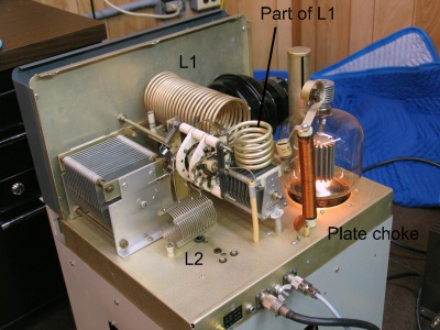
Original components. Note L2 is wound with quite small wire (16AWG), and also is quite large (10uH, compared to 5uH in my redesign). L1 is broken into two parts--the smaller part is for 10m, but is engaged for all bands. It's separated like that to keep the inductor Q high.
Full disclosure: this is not my photo nor my LK-2000. I believe this pic is on one of the Yahoo! amplifier groups. If it's yours tell me & you get full credit :-0
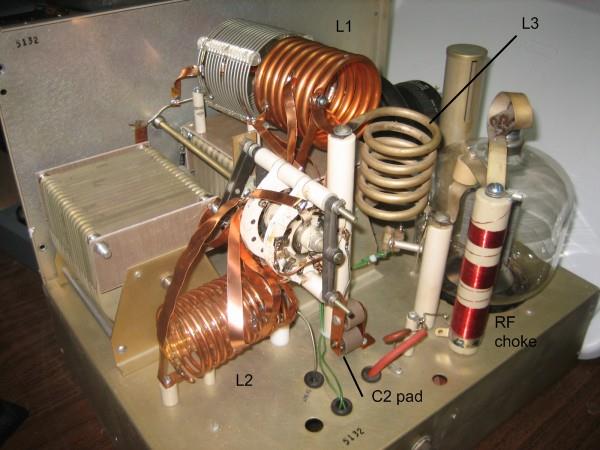
L1 is remade with variable wire diameter. Larger diameters increase component Q at higher frequency, but there is nearly no benefit to doing so on 80m and 40m.
The 1/4" copper tubing part is 20-10m.
The old "part of L1" is now L3.
L2 is remade with 8AWG wire.
C2 must be increased to decrease the image impedance. The "C2 pad" is a pair of 100pF/5kV N750 doorknob capacitors connected to the back switch wafer so that they are in parallel with C2 in the 80m position only.
And of course the new plate choke.
The coils were tapped by measuring them out-of-circuit with a Q-meter (to get close), and then fine-tuned using the same VNA measurement approach used to generate Table 1. Table 5 shows the measured results. Everything was fairly close, except that a bit more C1 was needed on the 12m-10m position than calculated. I think the tap on L2 must be a bit off the mark.
Table 1 Original Manufacturer component values and electrical design points
Table 2 Conventional redesign
Table 3. Effect of the "trick" inductor on effective anode impedance
Table 4 Final redesign values, including the "trick" inductor effects
Figure 1 Original LK-2000 RF deck
Figure 2 Modified LK-2000 RF deck
Figure 2 Modified LK-2000 RF deck
Construction
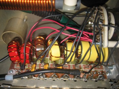
The original input bandswitch and input network assembly was removed. A good replacement bandswitch (if overrated) is the JV9001. It is 2 pole/8 position on a single wafer. The components are mounted on a homemade circuit board. The land areas were cut with a hobby knife and unwanted copper peeled away. Then slots were drilled for the capacitor tabs.
Inductors are realized with T-106 size cores, mix 2 for 80-40-30m and mix 6 for the higher bands. Part of the reason for sticking with toroids, even with only a couple of turns, is to reduce any coupling between adjacent inductances.
Capacitors are all ARCO 46 series mica trimmers (on the bottom) with 500V silver mica padders as needed (on the top).
Holes were drilled in the side of the amplifier chassis to have access to the trimmer capacitor adjustment screws (just visible beneath the board edge).
Figure 3 8-band input network
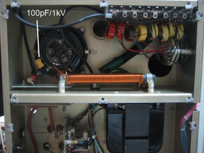
Figure 4 Input compartment, with 100pF cathode-ground capacitor shown
|
Band |
C1 (tune), indicated |
C2 (load), indicated |
Q_loaded |
|
80m |
42 |
84 |
10.1 |
|
40m |
8 |
38 |
10.9 |
|
30m (20m bandswitch) |
60 |
39 |
18.6 |
|
20m |
13 |
15 |
15.9 |
|
17m (15m bandswitch) |
26 |
18 |
20 |
|
15m |
0 |
12 |
18.3 |
|
12m (10m bandswitch) |
49 |
15 |
21.4 |
|
10m |
20 |
10 |
19.6 |
Table 5 Measurement of the final construction
Tuned Input Network
Adding bands to the input network involves the same choices as the output network expansion does: new bandswitch and components, a roller inductor, or reuse the existing input networks on the WARC bands.
Some would suggest reusing the existing input networks--after all, they are typically built with a fairly low Q (typically 2) and so should be pretty broadband. However, one thing I have noticed (along with others) is that cathode-driven amplifiers like the LK-2000 work much better when the input is well matched. The overall power efficiency and available power output is increased much more than a simple reflection analysis would indicate. In this case, I decided to go all-out and replace the existing tuned input network with a brand new, 8-band switch selected pi-network.
A few words about the original LK-2000 tuned input circuit. First, it's designed for a 50 ohm impedance on both input (to the exciter) and to the output (cathode-grid). Problem is, the 3-1000Z presents around 73 ohms impedance at full output, so the stock input network isn't quite on the mark (about 1.4:1 VSWR at best). Plus, with only one adjustable component (the slug-tuned coil), it's difficult to really hone in on a 1:1 match. That's part of the reason for completely rebuilding the tuned input.
Design Considerations
With the above comments in mind, each input circuit was designed for the actual 73 ohms of input resistance. The input capacitance of the tube is about 7pF, so that needs to be accounted for in the "output" pi capacitor. One other twist in the LK-2000 is that there is about 19" of RG-58 between the tuned input and the cathode. This coax length must be accounted for in the circuit design. 19" of RG-58 doesn't amount to much at 80m (as we will see), but it's quite significant at 10m. Perhaps another reason most amps' output falls off on 10m...
Another consideration is the dissipation of harmonic energy at the cathode. Since the grid current flows in pulses, it has significant components of power at the 2nd, 3rd, etc. harmonic frequencies. Nominally, the shunt capacitor on the "output" of the pi-network "shorts" this harmonic energy to ground (since the capacitive reactance decreases with increasing frequency). The 19" cable changes all that. Based on suggestions I've read on the internet, it makes sense to me to put some amount of shunt capacitance to ground directly at the cathode. My implementation puts a 100pF/1kV silver mica right on the tube socket (cathode-ground). The actual circuit design will have to consider this capacitor as well.
Design--First Iteration
The tube input impedance is easily calculated as 73 ohms resistance in parallel with 7pF cathode-ground capacitance. The transformed input impedance (the impedance the input network has to be designed for) includes both the 100pF shunt capacitor and the 19" of RG-58. Trivial work for the Smith chart...
|
Freq (MHz) |
Tube Input Impedance |
Transformed Input Impedance |
|
3.75 |
72.1-j2.1 |
67.2-j15.5 |
|
7.1 |
72.0-j3.9 |
57.3-j24.2 |
|
10.1 |
71.9-j5.6 |
47.5-j27.2 |
|
14.1 |
71.7-j7.8 |
36.2-j26.2 |
|
18.1 |
71.4-j10 |
27.7-j22.4 |
|
21.2 |
71.1-j11.8 |
22.9-j18.6 |
|
24.9 |
70.7-j13.8 |
18.6-j13.7 |
|
28.3 |
70.4-j15.7 |
15.6-j9.3 |
Table 6 Design impedance values for input network
Jim Tonne's Pi-EL program was again used to determine the component values (Table 7)
|
Freq (MHz) |
Cin, pF |
L, uH |
Cout, pF |
QL |
|
3.75 |
820 |
2.508 |
652 |
2.29 |
|
7.1 |
390 |
1.302 |
250 |
2 |
|
10.1 |
330 |
0.876 |
177 |
2.33 |
|
14.1 |
250 |
0.587 |
98 |
2.31 |
|
18.1 |
250 |
0.400 |
100 |
2.76 |
|
21.2 |
180 |
0.326 |
21 |
2.11 |
|
24.9 |
200 |
0.237 |
56 |
2.55 |
|
28.3 |
180 |
0.182 |
30 |
2.30 |
Table 7 Design component values for input network, first iteration
So I built it. To test it, I made a simple simulation fixture of two 150 ohm carbon composition resistors and a 7 pF silver mica capacitor with a 19" RG-58 pigtail. VNA measurements confirmed that the simulation fixture was very close to the "Transformed Input Impedance" values of Table 6. It tuned up great on 80m, took small effort on 40m, a bit of effort on 30m...and couldn't get it to play at all on 20m. Where did I go wrong?
Lesson 1: Lead inductance MATTERS in a low-impedance circuit
Before building the circuit, I did a quick check on if I needed to worry about lead inductance. For 16AWG wire, self-inductance is about 18nH per inch (0.018 uH). "That's nothing", I think to myself. "No need to account for that".
Except that (1) the wires aren't an inch long. I did (wisely) lay out the input board so that the 10m section was closest to the switch wafer (and so had the shortest connecting wires), but even those were about 2-1/2" long; and (2), the design inductances aren't so big themselves. On 10m, with two wires of about 2-1/2 inches (one for input and one for output), that's 5*18=90nH; the series inductor is only 182nH, so the wires are half the design inductance!
<Naughty language deleted>
Design--Second Iteration
Well, I'm not going to be able to eliminate the wire lengths, so I need to account for them in the circuit design. I measured the existing wire leads and recalculated Table 7. In this case, I'd either need to transform both the driver impedance (50 ohms) and the "Transformed Input Impedance" of Table 6 by the input and output wire series inductance, respectively; or I could be old-fashioned and use a Smith chart to calculate the values. I went old-school on this one.
|
Freq (MHz) |
Input wire, nH |
Cin, pF |
L, uH |
Cout, pF |
Output wire, nH |
|
3.75 |
200 |
1300 |
2.25 |
1000 |
230 |
|
7.1 |
175 |
850 |
1.03 |
650 |
220 |
|
10.1 |
150 |
600 |
0.7 |
450 |
210 |
|
14.1 |
125 |
510 |
0.41 |
450 |
200 |
|
18.1 |
100 |
380 |
0.3 |
420 |
190 |
|
21.2 |
100 |
295 |
0.255 |
380 |
180 |
|
24.9 |
100 |
255 |
0.24 |
425 |
180 |
|
28.3 |
100 |
250 |
0.23 |
400 |
180 |
Table 8 Design component values for input network, second iteration