Scott Townley
Bridgewater, NJ
NX7U
Introduction
This page describes the construction of the 2m 4CX1000A amplifier from the 1999 edition of the ARRL Handbook. The 4CX1000A is in a grid-driven, grounded-screen configuration, and uses two half-wave stripline resonators for grid and plate tuning. The main advantage of this particular configuration (versus the ever-popular 3CX1500A7/8877 "W6PO" amp) is that less than 10W drive gets you the US legal limit output (1.5 kW). The bummer in this particular project is that you literally build it by hand, piece-by-piece.
The Article - the starting point
The original article, with annotations by me, can be downloaded <here>. The annotations reflect some of the observations made during construction.
Lesson #1
It took me awhile, but here is an important lesson I learned during construction:
The guy who built this likely used readily available stuff. What he used is only one subset of what can work. The more you can answer "why did he use that particular piece/material/shape/placement", the better you can adapt your implementation to use YOUR readily available stuff.
Construction Begins...
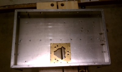
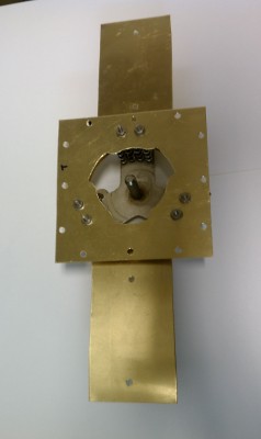
Chassis bottom, with socket top plate in place
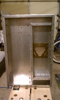
Chassis top. Starting to build the plate box/enclosure.
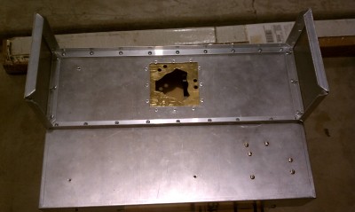
Chassis bottom. Starting to build the grid box/enclosure.
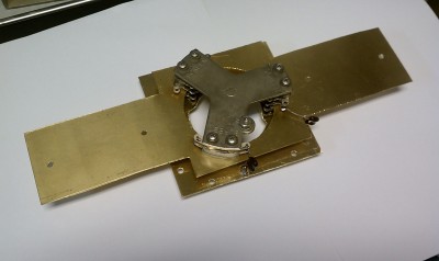
This was a mistake! Build the socket-grid line assembly before building/attaching the grid box!
Originally, my thinking was that I would build the socket plate, then build the socket "in-place" in the chassis/grid box. I wasted many many hours trying to do that. There is very little room to manouver with the grid box in place, and you can't really see what is going on with the socket assembly. In my case, I could never get the tube to fit the socket correctly. The grid tangs on the tube would never line up with the grid spring clips. Finally I gave up on the idea of building the socket "in-place", and made the socket plate/grid line/socket as a separate assembly.
In so doing I made some observations about the assembly of the socket that for whatever reason were not (or incorrectly) accounted for in the original Handbook article:
| • |
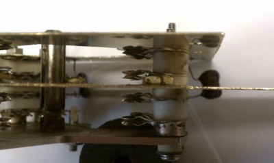
One of the ceramic spacers is "split"...two pieces, less than half-height of the "normal" spacers |
| • |
The "split" spacer is designed to fit around the bottom surface of the screen bypass capacitor that is build into the SK-800 socket. The capacitor is made of 0.020" silver-plated brass. |
| • |
The article does not explicitly show how to interface the grid line with the rest of the socket. But there is no way that the originally-specified 0.062" brass would work with my particular socket arrangement. One set of socket spring clips would be spaced too far. So I made my grid line and socket plate out of 0.025" brass (closest I could find). |
| • |
The callout hole in the grid line is too small to "sit" the grid spring clips onto (thus relying on physical contact for electrical continuity). The clips have some tensioning bends built into them which require the callout hole to be a bit larger to avoid pushing the clips away from horizontal. |
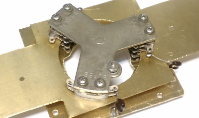
My implementation of the grid line/socket plate/socket as a subassembly. The heater and cathode bypass capacitors are in place. The 0.010" teflon and the opposite "plate" of the DC block are not assembled in these pictures.
Note the "split" spacers are on either side of the grid line. I soldered #6 brass nuts as "wires" to connect the grid spring clips to the grid line.
The main tests are: does the tube fit? Do all the tangs wedge into their spring clips? And do the screen tangs (pinching against the socket plate) capture the screen tangs of the tube?