Scott Townley
Bridgewater, NJ
Housebreaking the EFJohnson 6N2 Thunderbolt
NX7U
| • |
Screen and Grid Voltage Regulator replacement |
| • |
Heater delay timer and OPERATE relay |
| • |
Grid circuit modifications |
| • |
Integrated T/R RF relays |
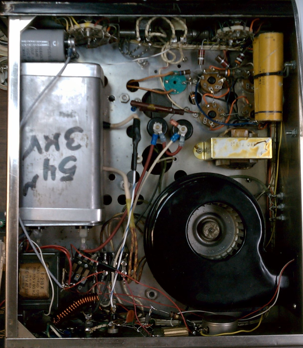
The Original Amplifier
Of particular note are the old paper electrolytic capacitors (orange) in the upper right corner. Those are for the screen supply. On the other side of the chassis are four gas regulator tubes (VR).
Hence the first order of business was to replace the regulator tubes and the capacitors with a more "modern" approach. A GM3SEK "tetrode" board would have been ideal, but chassis volume is at a premium. Therefore I built a simple diode stack.
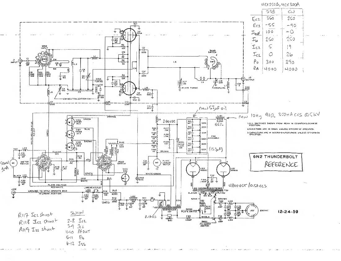
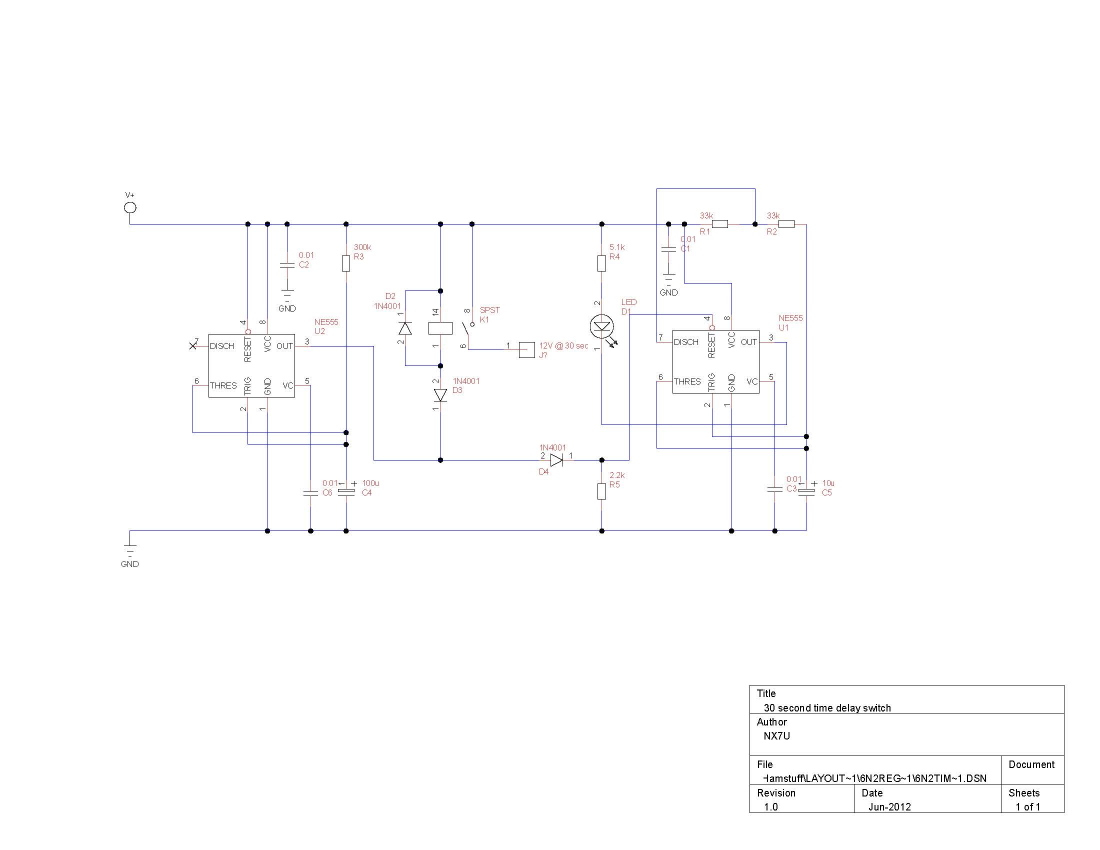
The reference schematic, reflecting my unit, with some notes on the switch arrangement and the intended operating parameters.
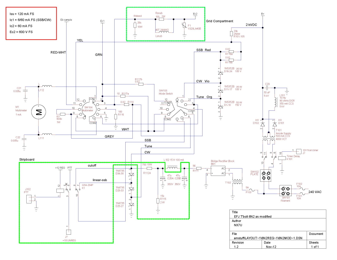
Above is the modified schematic.
First, the screen regulator: three of the VR tubes are replaced by a stack of 1N5352B zeners (D1-D24). Each zener is rated 15 volts and 5 watts dissipation. The stack is divided into three different voltages to support TUNE, CW, and SSB screen voltage requirements.
Second, the grid supply: the fourth VR tube is replaced by a stack of 1N4735 zeners (D25-D38). Each zener is rated 6.2 volts and 1 watt dissipation. Again, the stack is divided into three different voltages to support TUNE, CW, and SSB grid voltage requirements.
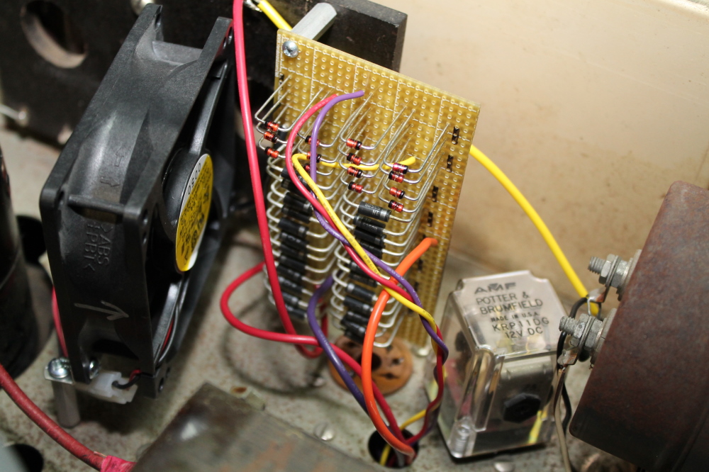
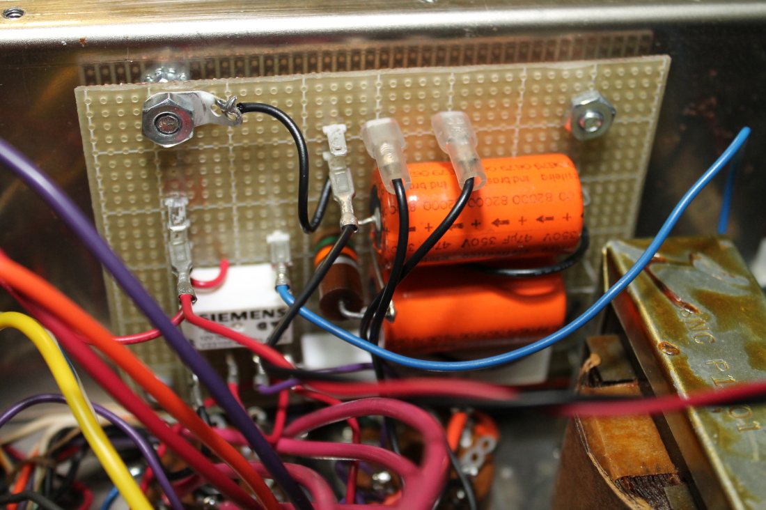
Both screen and grid regulators are built onto a single perfboard. Leads are kept as long as possible for heat sinking, and a small fan was added for cooling. The KRP11DG relay is part of the anode voltage time-delay circuit (further down the page).
The larger green outline on the modified schematic is for the screen supply filter capacitors (orange) and the grid bias relay. In this arrangement, the tubes are cutoff in RX. Of course, for CW 'cutoff' is the operating condition (Class C).
Not shown on the modified schematic is the addition of a 30 second time delay switch. This circuit enforces a 30 second delay from the time heater voltage is applied to the tubes, to the time the anode voltage is activated. K1 is visible to the right of the screen & grid zener diode regulators a few pictures back.
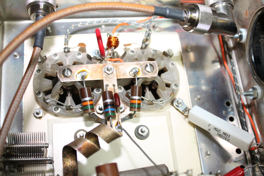
Screen supply protection components as shown in the topmost green outline in the modified schematic ("grid compartment"): bleed resistor (white cement resistor to the right), voltage snubber and varistor/MOV just above the "tee" junction.
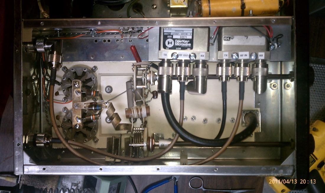
A constant consideration with any vintage amplifier is the provisioning of T/R relays to support the use of transceiver exciters. Rather than make them "optional" I built them in permanently.
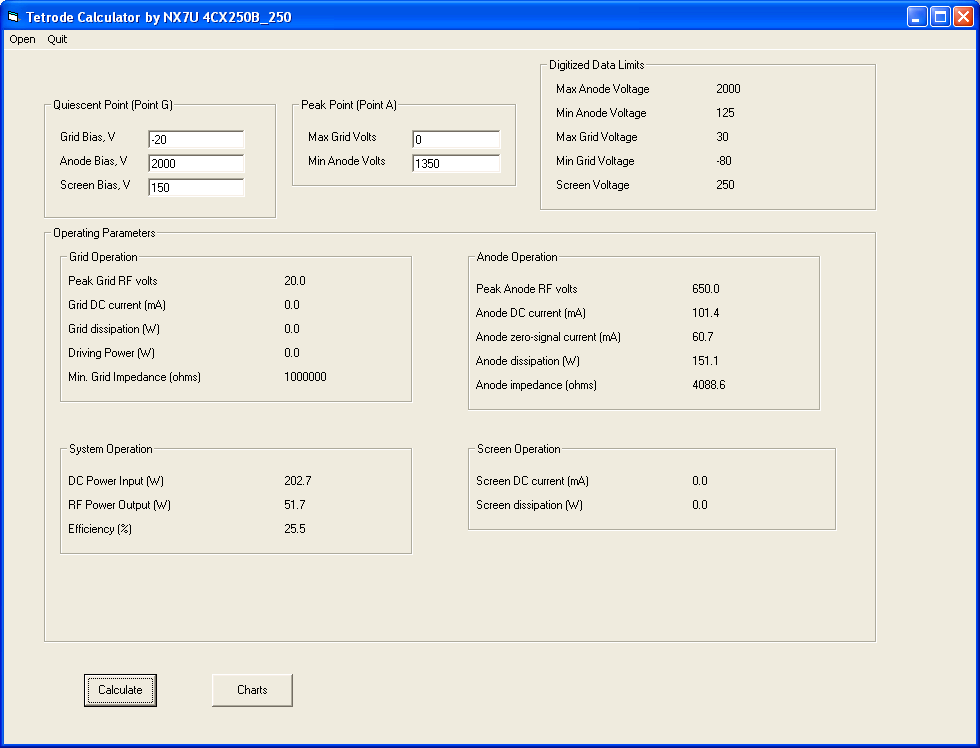
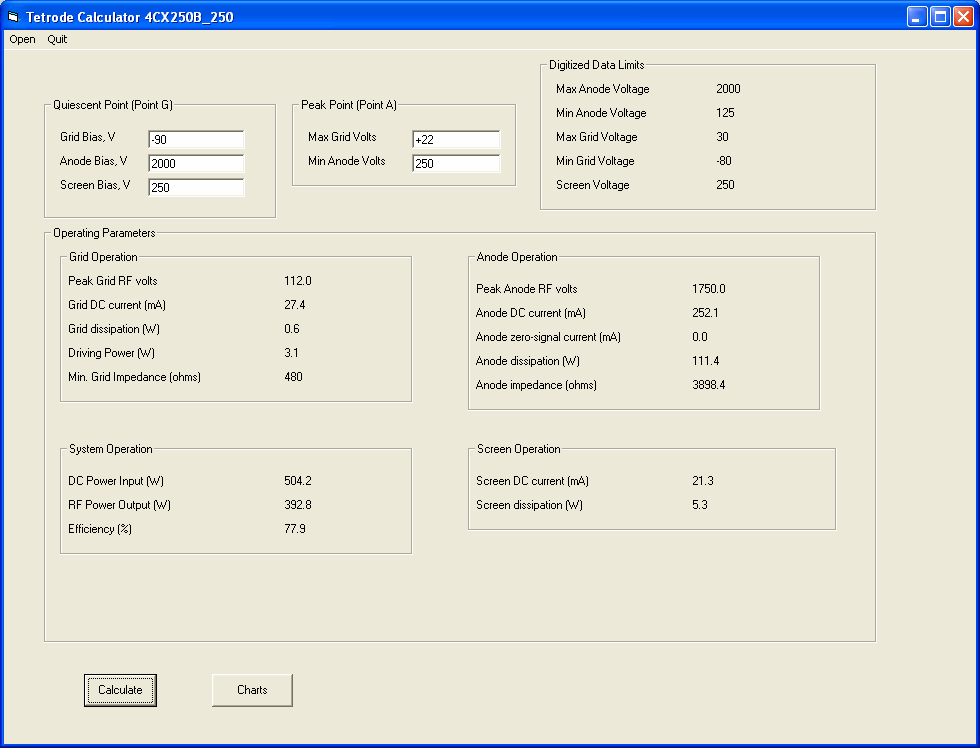
Operating Conditions
Calculated using my "Tetrode" program (see the Software section of this website)
TUNE mode
CW mode (class C)
SSB mode (class AB1--no grid current!!)