NX7U
Scott Townley
Bridgewater, NJ
Originally I started with a 9-element vertically polarized yagi (1/2 of a M2 440-18 yagi). Operating during the summer of 2002 with very high squints (although very low altitudes) and the attendant QSB on the uplink drove me to make the move to circular polarization on transmit as well. The 1/2-yagi was only about 4' of boom, so I decided to go for a bit more boom length as well for additional gain. In the end I settled on a 12-turn helix for about an 8' (2-1/2m) boom as a decent compromise.
The helix has a 1" (2.5cm) square aluminum boom and uses 1/2" (1.25cm) PVC pipe as the occasional spacer. Originally I built it with the "standard" sheet reflector at the feedpoint, but never fielded it. It was a royal pain in the bum to mount the reflector, and since my tripod mount is "free-wheeling" (has no brake or other stopping mechanism against wind) I wasn't thrilled with putting up more sail area.
And then I found this:
Kraus, J. D., "A Helical-Beam Antenna Without a Ground Plane", IEEE Antennas and Propagation Magazine, Vol. 37, No. 2. April 1995, p. 45
Looking over the description of the antenna that Dr. Kraus had built, it looked just like what I wanted...a helix with all the properties (polarization, impedance, pattern) maintained, but using one (or more) closed-circular loop reflectors instead of a solid sheet (or the common spoke-and-screen). The following pictures show how it turned out; dimensions follow the pictures.
U-band (435 MHz) Helix for Satellite Uplink
(Originally designed for AO-40)
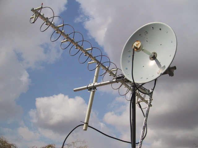
The complete AO-40 setup with the U-band helix to the left. A 60cm dish to the right was used for the S-band downlink.
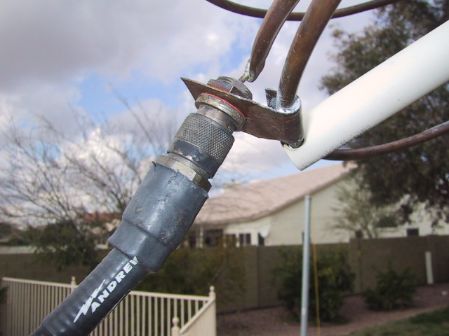
Here is a closeup of the feed arrangement. The helix progresses to the lower left of the picture. Directly behind the end of the helix is a closed loop of the same diameter as the helix, and another closed loop about 1/3 wavelength away (you can just see a bit of it in the far upper right hand of the photo).
The feedpoint is just a bit of copper flashing wrapped around the first reflector loop and soldered. On the flashing is mounted a hermetic N-type panel connector (what I had laying around). The other side of the flashing is just a #12 wire soldered from the panel nipple to the end of the helix.
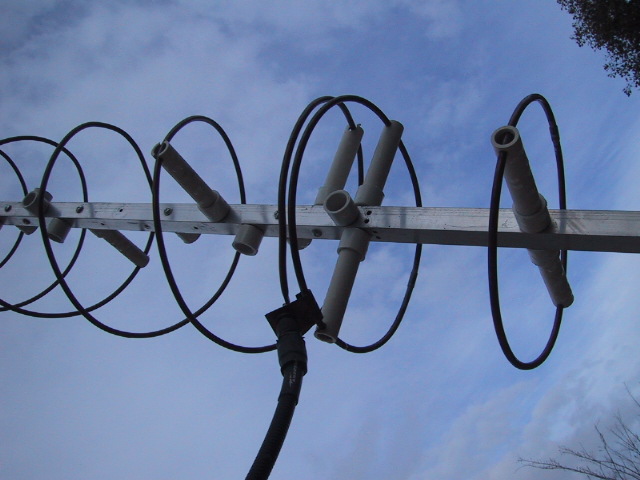
Here you can see the second reflector on the right, and the helix progressing on the left.
Note how the 1st quarter-turn or so of the helix (mostly) parallels the ground loop, rather than taking off right away. That is an attempt at an impedance matching section. It seems to work OK, on my Autek VHF impedance meter I got a 1.7:1 VSWR "out of the box". Wasn't worth messing with beyond that.
Dimensions of the "Helical Beam Antenna Without a Ground Plane" for 435MHz
Reflector loops and helix radius 4.7"
Conductor diameter is 0.25" (used copper refrigeration tubing)
Reflector #2 spacing from reflector #1/feed point 6.8"
Helix turn spacing 6.4375"
Number of turns=12 Axial Length=83.7" Pitch angle=12.3 degrees
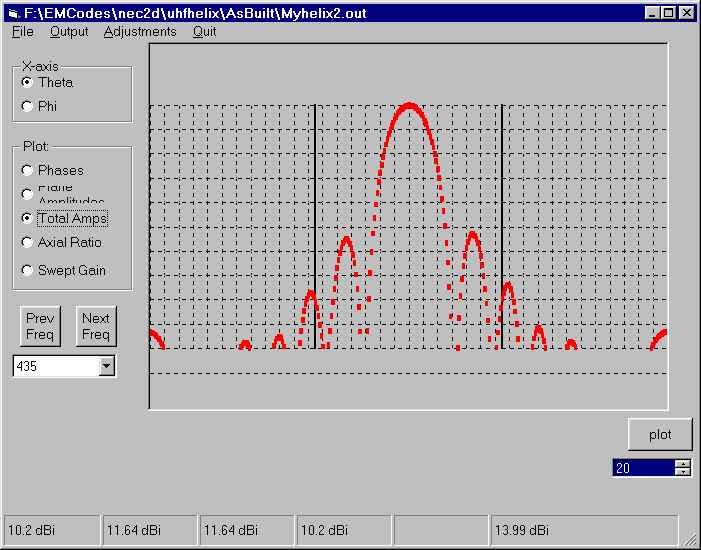
NEC-2 modelled radiation pattern, showing just under 14 dBiC gain.
Horizontal axis is in 10 degree increments.
Vertical axis is in 2 dB increments.
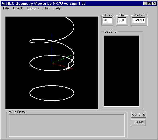
Visualization of the wire grid model used in NEC-2. This model does not reflect the parallel section noted above.


")
")