NX7U
Scott Townley
Bridgewater, NJ
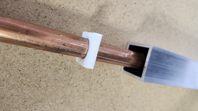
The outer conductor/square tubing is 1-1/2" outside and 1-1/4" inside (0.125" wall), cut to 1/4 wavelength.
The inner conductor is a nominal 5/8" copper pipe, which has an outside diameter of 0.75". This was probably a mistake, as there is no reason to use copper as the inner. 5/8" copper isn't a commonly found item, while 3/4" aluminum tubing is trivial.
The spacer shown is 1/4" thick PTFE, hand-cut to fit the outer and inner. The inner hole was cut with a chassis punch.
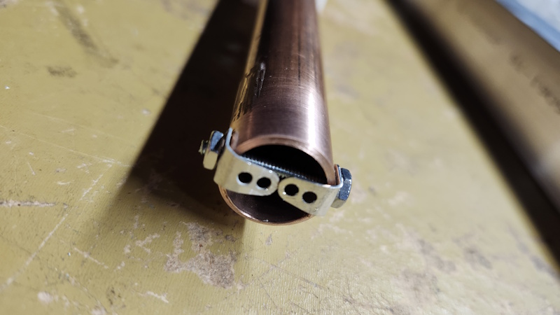
The real challenge is: how do you mechanically and electrically bond the connector center pins to the inner? One could solder them directly to the copper but that's going to be quite difficult to do with the inner in place. I saw this trick on the internet to provide a solderable surface that's mechanically rigid.
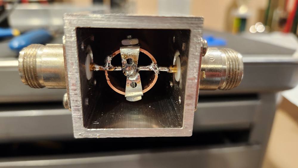
The finished product. I found cool square aluminum caps (intended for fence posts) on Amazon.
Measurements
Measurements of the combiner performance were made using an SDR-Kits VNWA calibrated with Kirkby Microwave cal kit.
My measured insertion loss (S21) was 3.19 dB and I'm not sure if that's to be expected. In my mind I say "two connectors probably 0.05 dB each, plus the combiner itself another 0.1 dB so it's as good as you'll be able to homebrew" but I don't want to fool myself if there is some way to get back 0.1 dB. The return loss (S11) was only about 25 dB, which is bit on the high side (closer to zero). Of course a higher return loss will show up as a higher insertion loss as well.
After some thinking I decided to make some more measurements on the transmission line itself.
The first measurement was to measure the input impedance with the other end open-circuited, then short-circuited. In this case I only short-circuited one output port, accepting that the other output isn't exactly "open" but it's close. From those two measurements you can find (the complex) Z0 and the attenuation constant. The result was Z0=32.827+j0.056393, and alpha (from gamma=alpha+j*beta) of 0.00736 Np/m or 0.06386 dB/m. Since it's a quarter-wave splitter the line length is very close to 0.5m, so the total ohmic loss is 0.0319 dB...I'd like to believe that is true!!
A second measurement was to load both outputs with some impedance, widen the sweep, and see where the resulting "circle" on the Smith chart crossed the real axis (equivalently, the magnitudes of S11 when they are real). From that result, Zo=sqrt(Z1Z2).
Measurement 1, with 25 ohms loading both output ports: Z0=34.81 ohms.
Measurement 2, with 50 ohms loading both output ports: Z0=34.78 ohms.
Then to measure the attenuation constant, when short-circuiting one combiner output (see note above) and measuring the magnitude of S11 at 145 MHz with the Smith chart normalized to the measured Z0 (34.8 ohms), I got alpha=0.067 dB/m, very close to the first measurement (reference for this second measurement: Munk, Metamaterials: Critique and Alternatives, Wiley, 2009, Appendix C).
As far as Zo goes, my input resistance with both output ports loaded in 50 ohms is 44.8 ohms (RL=25 dB), implying that the transmission line Zo is sqrt(44.8*25)=33.466 ohms, which is closer to the first measurement. Note that all measurements were lower than the targeted 35.355 ohms, which is going to impact the return loss.
As far as the attenuation constant goes, since both measurements incorporate using a short-circuit at the combiner end, with that (open) 2nd connector hanging off of the junction, I suppose it's not surprising that the results are in good agreement. And I know I'm likely pushing the VNWA to (or past!) its limits in measuring these large reflection coefficients.
Surely I can make something rather than just buy it all...


")
")