Items for Sale
Last Updated: 21 September 2013
General Terms
Feel free to counteroffer on any or all items. I may laugh, I may not...
I accept PayPal or US Postal Service Money Orders for any items.
Shipping and insurance costs are the buyer's responsibility. I prefer to ship US Postal Service, but it's your nickel, so if you have a preferred carrier, let me know.
All items are in working condition unless otherwise indicated.
International buyers are welcome, but please note that VAT/duty/customs are your responsibility, and I will not misrepresent any items on a customs form.
Transmitters and amplifiers are for sale to licensed amateurs only.
E-mail me at <callsign> at nx7u.net
Delta Electronics OIB-2 Operating Impedance Bridge
$1800
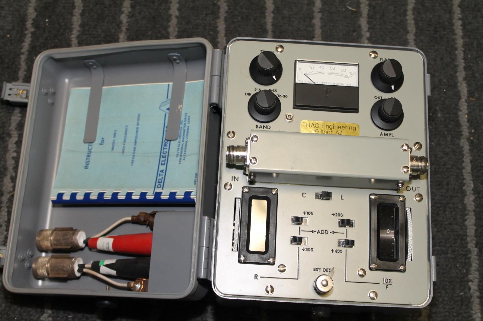
Excellent, dare I say near-mint, condition. Complete (as shown) with test leads and instruction manual.
This is also known as a "hot bridge". The idea is that you can measure the impedance of an antenna element WHILE OPERATING...that is, under full transmit power. This is critical for adjusting four-squares or other arrays of elements with significant mutual coupling and interaction.
------------------
Straight from the manual:
General Description:
The Delta Electronics, Inc. Model OIB-2 High Frequency Operating Impedance Bridge is an impedance measuring instrument based on a new bridge principle. It permits the measurement of impedance under power, with a minimum of insertion effects on the circuit being measured. The bridge will handle a through power of up to 1,000 watts at moderate standing wave ratios. Resistance and reactance values are read directly from two drum dials located on the front of the panel. An internal detector is provided so that when the bridge is operating in a power circuit, no other instrument is required.
Operating Impedance:
The term "operating impedance" is defined as the complex ratio of the voltage applied to a load to the current flowing in the load when it is operating under normal power and in its normal environment. In many cases, this impedance differs substantially from the "self-impedance" or "cold impedance" of the load. In antenna systems, for example, a separate radiator has a self-impedance when operating in free space. When it is combined in an antenna array, its operating impedance differs from its self-impedance by the coupled impedances from adjacent radiator elements, or its image.
Many loads have an operating impedance which differs with applied power level. In dielectric heating applications, for example, the operating impedance of the dielectric varies substantially with applied power. Meaningful impedance measurements must, therefore, be made at normal power level.
Differences Between Bridges:
The Delta Electronics, Inc. Model OIB-2 High Frequency Operating Impedance Bridge differs from bridges based on classical design, in that the bridge can handle a substantial power level and causes a minimum of insertion effects. This permits the direct measurement of operating impedance as defined above. For example, in the dielectric heating problem cited above, the Model OIB-2 can be inserted directly in the circuit and the operating impedance of the load measured under normal power. Bridges of a classical design are ordinarily incapable of handling large amounts of power. They measure the "cold" impedance of the load. When the matching circuits are adjusted from these measurements, it is found that a satisfactory match is not obtained when power is applied.
In measuring the operating impedance of various elements of a complex directional antenna, the installation of a normal bridge within the antenna circuit completely disturbs the relative magnitude and phase of the currents in the various radiators. The element under measurement, therefore, does not have the normal coupled impedance, and the measurements made do not give an impedance value which can be used to adjust the feeding system of the antenna. The Model OIB-2 impedance bridge, on the other hand, can be installed directly invthe circuit of each element, each transmission line, each matching network, etc., and the operating impedance level throughout the system can be determined. The data thus obtained can be used to match the entire antenna system and determine the power level throughout the complete system. Another distinct advantage of the OIB-2 is that a signal generator of substantial power can be used with the bridge for making antenna impedance measurements. The interference effects from adjacent antennas in operating, or from strong signals on nearby frequencies, can thus be minimized. This permits measurements in an antenna "farm" that would otherwise require closing down the entire station.
Specifications:
Frequency Range: 2 mc to 30 mc.
Through Power Rating: 1 kw with VSWR 3.
Insertion Effects: Equal to 5" of 150-ohm line.
Functions (10 mc):
Dir. Reading in R: -400 to +400 ohms.
Dir. Reading in X: -400 to +400 ohms.
Accuracy: R & X, ±5% ±1 ohm.
RF Source: Transmitter, transmission lines, etc., or signal generator with adapting connector.
Detector: Internal for power sources, BNC connector on front panel for external detector when used with signal generator.
Terminals: Input and output are Type N receptacles. 6" output clip leads supplied with bridge - external detector connection is BNC.
Dimensions and Weight: 9" high x 7" wide x 6-1/4" deep, 8 lbs (228.6 mm high x 177.8 mm wide x 158.8 mm deep, 3.6 kg)